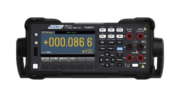
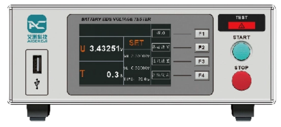
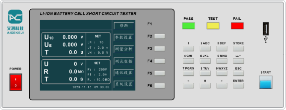
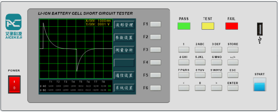
Model | AC3065 |
Product Name | Wide-Range Edge Voltage Tester |
Range2/Frequency / DC Voltage | 24 Hours³
TCAL±1℃ | 90 Days | 1 Year | 2 Year | Temp. Coeff./℃⁴ |
TCAL±5℃ | TCAL±5℃ | TCAL±5℃ |
100 mV | 0.0030+0.0030 | 0.0040+0.0035 | 0.0050+0.0035 | 0.0065+0.0035 | 0.0005+0.0005 |
1V | 0.0020+0.0006 | 0.0030+0.0007 | 0.0040+0.0007 | 0.0055+0.0007 | 0.0005+0.0001 |
10V | 0.0015+0.0004 | 0.0020+0.0005 | 0.0035+0.0005 | 0.0050+0.0005 | 0.0005+0.0001 |
100 V | 0.0020+0.0006 | 0.0035+0.0006 | 0.0045+0.0006 | 0.0060+0.0006 | 0.0005+0.0001 |
1000 V | 0.0020+0.0006 | 0.0035+0.0010 | 0.0045+0.0010 | 0.0060+0.0010 | 0.0005+0.0001 |
True-RMS AC Voltage2,5,6 |
100 mV, 1 V, 10 V, 100 V, and 750 V Ranges |
5 Hz-10 Hz | 0.35+0.02 | 0.35+0.03 | 0.35+0.03 | 0.35+0.03 | 0.035+0.003 |
10 Hz-20 KHz | 0.04+0.02 | 0.05+0.03 | 0.06+0.03 | 0.07+0.03 | 0.005+0.003 |
20 KHz-50 KHz | 0.10+0.04 | 0.11+0.05 | 0.12+0.05 | 0.13+0.05 | 0.011+0.005 |
50 KHz-100 KHz | 0.55+0.08 | 0.60+0.08 | 0.60+0.08 | 0.60+0.08 | 0.060+0.008 |
100 KHz-300 KHz | 4.00+0.50 | 4.00+0.50 | 4.00+0.50 | 4.00+0.50 | 0.200+0.020 |
Resistance7 | Test Current |
100 Ω | 1 mA | 0.0030+0.0030 | 0.008+0.004 | 0.010+0.004 | 0.012+0.004 | 0.0006+0.0005 |
1 KΩ | 1 mA | 0.0020+0.0005 | 0.008+0.001 | 0.010+0.001 | 0.012+0.001 | 0.0006+0.0001 |
10 KΩ | 100μA | 0.0020+0.0005 | 0.008+0.001 | 0.010+0.001 | 0.012+0.001 | 0.0006+0.0001 |
100 KΩ | 10 μA | 0.0020+0.0005 | 0.008+0.001 | 0.010+0.001 | 0.012+0.001 | 0.0006+0.0001 |
1 MΩ | 5μA | 0.002+0.001 | 0.008+0.001 | 0.010+0.001 | 0.012+0.001 | 0.0010+0.0002 |
10 MΩ | 500 nA | 0.015+0.001 | 0.020+0.001 | 0.040+0.001 | 0.060+0.001 | 0.0030+0.0004 |
100 MΩ | 500 nA||10 MΩ | 0.300+0.010 | 0.800+0.010 | 0.800+0.010 | 0.800+0.010 | 0.1500+0.0002 |
DC Current | Internal Resistance Voltage Drop |
100 μA | <0.11V | 0.010+0.020 | 0.040+0.025 | 0.050+0.025 | 0.060+0.025 | 0.0020+0.0030 |
1 mA | <0.11V | 0.007+0.006 | 0.030+0.006 | 0.050+0.006 | 0.060+0.006 | 0.0020+0.0005 |
10 mA | <0.05V | 0.007+0.020 | 0.030+0.020 | 0.050+0.020 | 0.060+0.020 | 0.0020+0.0020 |
100 mA | <0.5V | 0.010+0.004 | 0.030+0.005 | 0.050+0.005 | 0.060+0.005 | 0.0020+0.0005 |
1 A | <0.7 V | 0.050+0.006 | 0.080+0.010 | 0.100+0.010 | 0.120+0.010 | 0.0050+0.0010 |
3 A | <2.0V | 0.180+0.020 | 0.200+0.020 | 0.200+0.020 | 0.230+0.020 | 0.0050+0.0020 |
10 A8 | <0.5V | 0.050+0.010 | 0.120+0.010 | 0.120+0.010 | 0.150+0.010 | 0.0050+0.0010 |
Capacitance15 |
1.0000 nF | 0.50+0.50 | 0.50+0.50 | 0.50+0.50 | 0.50+0.50 | 0.05+0.05 |
10.000 nF | 0.40+0.10 | 0.40+0.10 | 0.40+0.10 | 0.40+0.10 | 0.05+0.01 |
100.00 nF | 0.40+0.10 | 0.40+0.10 | 0.40+0.10 | 0.40+0.10 | 0.05+0.01 |
1.0000μF | 0.40+0.10 | 0.40+0.10 | 0.40+0.10 | 0.40+0.10 | 0.05+0.01 |
10.000 μF | 0.40+0.10 | 0.40+0.10 | 0.40+0.10 | 0.40+0.10 | 0.05+0.01 |
100.00μF | 0.40+0.10 | 0.40+0.10 | 0.40+0.10 | 0.40+0.10 | 0.05+0.01 |
Range2/Frequency | 24 Hours³ | 90 Days | 1 Year | 2 Year | Temp. Coeff./℃4 |
TCAL±1℃ | TCAL±5℃ | TCAL±5℃ | TCAL±5℃ |
True RMS AC current2,6,9 | Internal Resistance Voltage Drop |
100 μA, 1 mA, 10 mA, and 100 mA Ranges | <0.011,<0.11,<0.05,<0.5V |
3 Hz-5 KHz | 0.10+0.04 | 0.10+0.04 | 0.10+0.04 | 0.10+0.04 | 0.015+0.006 |
5 KHz-10 KHz (Typical) | 0.10+0.04 | 0.10+0.04 | 0.10+0.04 | 0.10+0.04 | 0.030+0.006 |
1 A Range | <0.7 V |
3 Hz-5 KHz | 0.10+0.04 | 0.10+0.04 | 0.10+0.04 | 0.10+0.04 | 0.015+0.006 |
5 KHz-10 KHz (Typical) | 0.10+0.04 | 0.10+0.04 | 0.10+0.04 | 0.10+0.04 | 0.030+0.006 |
3 A Range | <2.0V |
3 Hz-5 KHz | 0.23+0.04 | 0.23+0.04 | 0.23+0.04 | 0.23+0.04 | 0.015+0.006 |
5 KHz-10 KHz (Typical) | 0.23+0.04 | 0.23+0.04 | 0.23+0.04 | 0.23+0.04 | 0.030+0.006 |
10 A Range8 | <0.5V |
3 Hz-5 KHz | 0.15+0.04 | 0.15+0.04 | 0.15+0.04 | 0.15+0.04 | 0.015+0.006 |
5 KHz-10 KHz (Typical) | 0.15+0.04 | 0.15+0.04 | 0.15+0.04 | 0.15+0.04 | 0.030+0.006 |
Continuity |
1 KΩ | 0.002+0.030 | 0.008+0.030 | 0.010+0.030 | 0.012+0.030 | 0.0010+0.0020 |
Diode Test10 |
5V | 0.002+0.030 | 0.008+0.030 | 0.010+0.030 | 0.012+0.030 | 0.0010+0.0020 |
DC Ratio (Typical) |
(Normalized Accuracy Input) + (Normalized Reference Accuracy) |
Temperature11 |
PT100(DIN/IEC751) | Probe Accuracy +0.05℃ |
5 KΩ Thermistor | Probe Accuracy +0.1℃ |
Frequency: Specifications ±(% Reading)12,13 |
100 mV, 1 V, 10 V, 100 V, and 750 V Ranges14 |
3 Hz-10 Hz | 0.1 | 0.1 | 0.1 | 0.1 | 0.1 |
10 Hz-100 Hz | 0.03 | 0.03 | 0.03 | 0.03 | 0.035 |
100 Hz-1 KHz | 0 | 0.008 | 0.01 | 0.01 | 0.015 |
1 KHz-300 KHz | 0.002 | 0.006 | 0.01 | 0.01 | 0.015 |
Square Wave15 | 0.001 | 0.006 | 0.01 | 0.01 | 0.015 |
Additional Gate Time Error ±(% Reading)13 |
Frequency | 1 s | 0.1 s | 0.01 s |
3 Hz-40 Hz | 0 | 0.2 | 0.2 |
40 Hz-100 Hz | 0 | 0.06 | 0.2 |
100 Hz-1 KHz | 0 | 0.02 | 0.2 |
1 KHz-300 KHz | 0 | 0.004 | 0.03 |
Square Wave15 | 0 | 0 | 0 |
1. For DC: Specifications are valid after a 60-minute warm-up, with integration time set to 10 or 100 PLC and auto-zero enabled. For AC: Specifications are valid after a 60-minute warm-up, with slow AC filtering and sinusoidal input.
2. Except for 1,000 V DC, 750 V AC, 10 A DC, 3 A AC, 10 A AC, and the diode test,all ranges feature 20 % overrange.
3. Relative to calibration standards.
4. Outside the TCAL ±5 °C range, an additional coefficient applies for each 1 °C deviation.
5. Specifications are valid for sine-wave inputs >5% of range and >1 mV RMS. The 750 V AC range is limited to 8 × 10⁷ V·Hz. If the input signal frequency is <50 kHz and the sine-wave input is between 1% and 5% of full range, an additional 0.1% error applies. For frequencies between 50 kHz and 100 kHz, an additional 0.13% error applies.
6. Low-frequency performance: Three filter settings are provided—3 Hz, 20 Hz, and 200 Hz. Frequencies above the filter setting are specified with no additional error.
7. Specifications apply to 4-wire or 2-wire resistance measurements (with NULL zeroing). Without NULL zeroing, 2-wire resistance measurements incur an additional 0.2 Ω error.
8. The 10 A range is available only via the front‑panel connectors. Each amplifier sources 2 mA base current for input current >5 Arms.
9. Specifications are valid for sine wave inputs >1.5% of range and >10 μA AC.
10. Specifications apply to the voltage measured at the input terminals. The 1 mA test current is typical. Changes in the current source will cause the voltage drop across the diode junction to vary.
11. The selected probe limits the actual measurement range and measurement error. Probe accuracy includes all measurement and ITS-90 temperature conversion errors. PT100Ro can be set to 100 Ω ±5 Ω to eliminate the original probe error.
12. Unless otherwise specified, specifications are valid after a 60-minute warm-up with a sine wave input. Specifications apply to a 1 s gate time (7 digits).
13. Valid for sine wave and square wave inputs ≥100 mV. For input signals from 10 mV to 100 mV, multiply the specifications by 10 (i.e., the reading specifications are increased by a factor of 10).
14. The amplitude range is 10% to 120% for voltages below 750 V AC.
15. Square wave input is specified from 10 Hz to 300 kHz.
* Due to layout limitations, only best‑selling models are shown.Contact us for a complete product selection.